Wiring of Digital Outputs (X15, X24)
Digital I/O connectors X15A, X15B on MKD-C and X24A, X24B on MKD-N supply programmable digital outputs, I/O Connection. Choose the required function in WorkBench. A list of these pre-defined functions can be found there. If the output is to be assigned to a pre-defined function, then the parameter set must be saved in the device memory.
Transistor Outputs (X15B, X24)
Technical characteristics:
- As per IEC61131-2 type 1
- Floating, max. 30 VDC, 100 mA
- Short circuit proof
- Galvanic isolation for 250 VDC
- Can be wired as sink or source (see examples below)
- Update rate: 250 µs
Wiring diagram:
![]()
* On MKD-N connector X24A is used for axis 1, X24B is used for axis 2 if built-in.
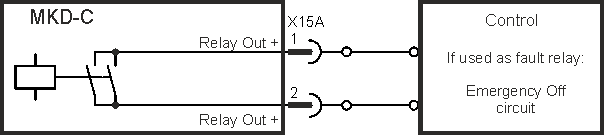
Relay Output (X15A)
Operational readiness can be signaled by these floating relay contacts. With the relay output set to be a fault relay, there are two modes of operation:
- Contact closed when there is no fault
- Contact closed when there is no fault and the drive is enabled.
Technical characteristics:
- Relay output, max. 30 VDC or 42 VAC, 1 A
- Time to close: max. 10 ms
- Time to open: max. 10 ms
Wiring diagram:
STO Status Outputs (X15A, X24)

|
STO Status signals can be used for information only. The signals should not be used for functional safe operations. For detailled description of STO functionality refer to STO (Safe Torque Off). |
Technical characteristics:
- As per IEC61131-2 type 1
- Floating, max. 30 VDC, 100 mA
- Short circuit proof
- Galvanic isolation for 250 VDC
- Can be wired as sink or source (current sourcing in the example below)
- Update rate: 250 µs
Wiring diagram:
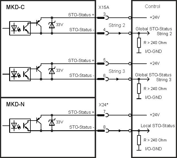
* On MKD-N connector X24A is used for axis 1, X24B is used for axis 2 if built-in.